Table of contents
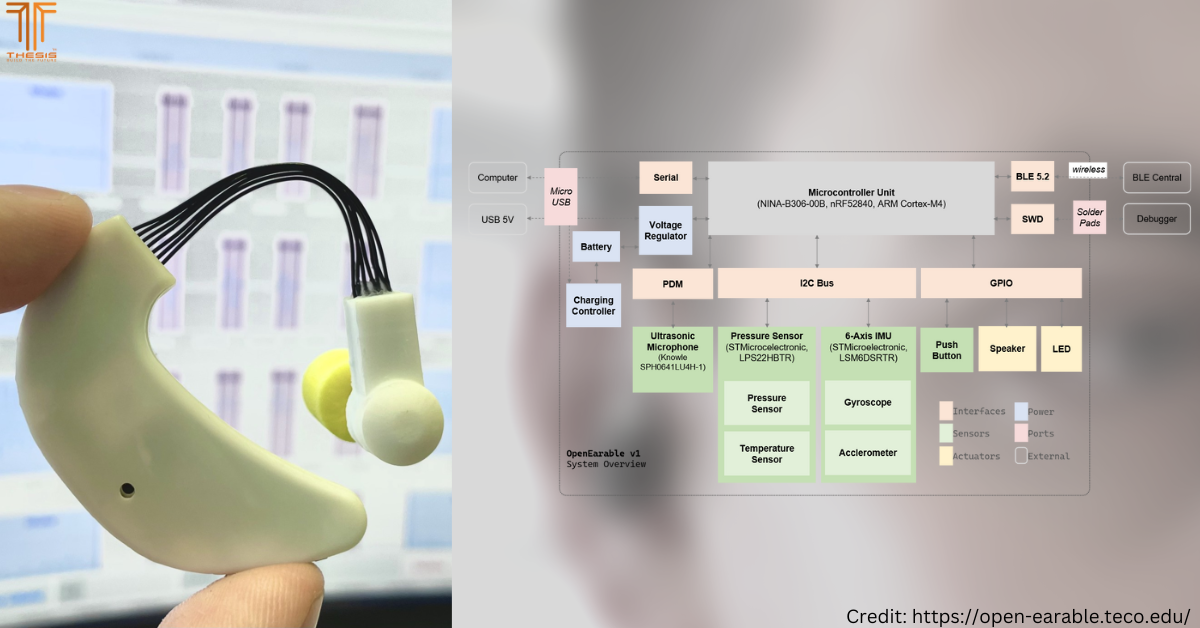
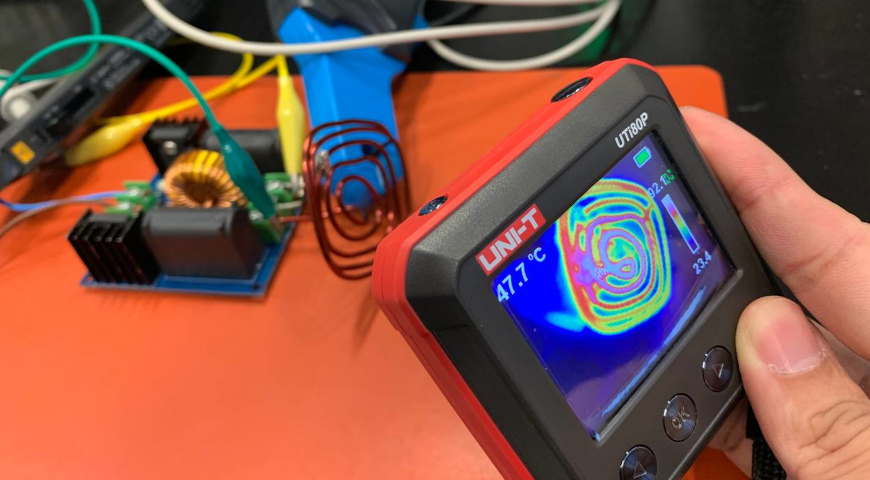
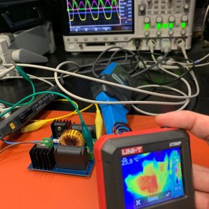
Here we show the waveform of a zero-voltage switching (ZVS) inductive heating circuit and the thermal profile in operation.
A typical buck regulator DC-DC is challenging to design when there is a significant voltage difference between the input and the output voltages. A significant voltage difference typically increases switching losses and limits the device's switching frequency. As a result, a non-isolated buck-voltage regulator would experience high switching losses because high currents and voltages simultaneously load the MOSFET during the on and off phases. To mitigate this, designers may use more than one MOSFET stage to achieve the desired performance. For example, 19 V to 1.8 V is a voltage drop that may require two regulation stages, which would demand more board space and force designers to use larger filtering components.
Zero voltage switching
One solution that allows a return to a faster switching frequency at a higher input voltage and a lower voltage drop is zero voltage switching (ZVS). This technique uses pulse width modulation (PWM) or resonant technique but with an additional separate phase for the switching signal to enable ZVS operation. ZVS allows the voltage regulator to switch "smoothly", avoiding the switching losses that typically occur with conventional PWM operation and timing.
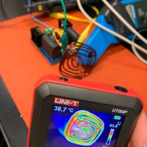
Zero-voltage switching (ZVS) inductive heating
One application of a zero-voltage switching is to act as an inductive heater, aka Zero-voltage switching (ZVS) inductive heating. In this project, our client provided their custom coil for us to measure the efficiency of the ZVS circuit with their custom coil. As ZVS can also be formed using a resonant circuit, the inductance of the coil directly affects the resonant frequency.
How to calculate resonant frequency
To calculate the resonant frequency of such a circuit, one can use the following formula:
Resonant frequency (Hz) = 1 / (2 x pi x (inductance x capacitance)^0.5). Inductance is the coil inductance, and capacitance is the capacitor designed for the ZVS circuit.
Our evaluation
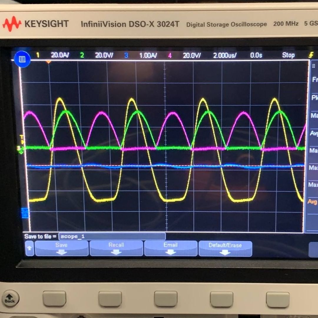
In the above circuit, the coil has a measured inductance of ~1uH at 100KHz, and the ZVS has two parallel 0.33uF capacitors, which equals 0.66uF. As a result, the resonant frequency is estimated around 196KHz. This matches quite closely with the resonant frequency being probed on the circuit.
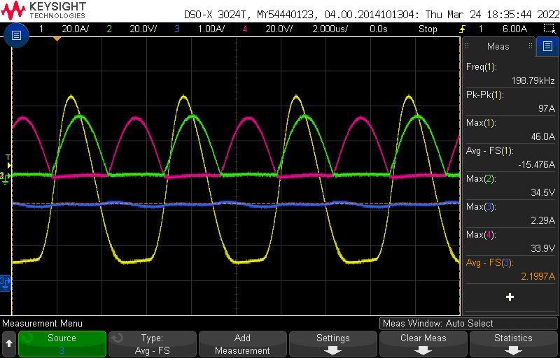
Green = Inductive coil voltage at one end
Blue = System Current
Red = Inductive coil voltage at the other end
The above diagram makes it easy to appreciate why it is called zero voltage switching because the switch only occurs when one end of the voltage goes to 0V (See Green and Red). A typical buck-switching MOSFET-based regulator would have higher overlapping during switching, which is power loss.
Gate switching voltages
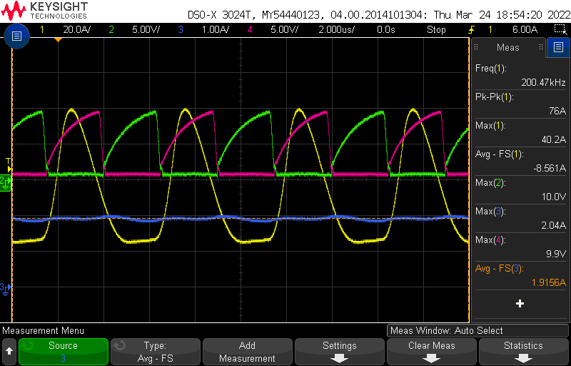
Green = Mosfet 1 gate pin
Blue = System Current
Red = Mosfet 2 gate pin
The above snapshot displays the gate switching voltages, and we can assume that the MOSFET may not have a chance to enter saturation mode. We speculated here because the circuit is rated for higher current, and we also do not have the part number for the MOSFET. Back to the topic, without entering the saturation region, the MOSFET would not be able to allow the maximum amount of current to flow into the coil and limit its heating capability. However, by operating in linear mode, the MOSFET remains relatively "cool" and prevents thermal runaway. To tune such a circuit, the designer must tradeoff between current capability and heat buildup. This is also why designers should have a heatsink placed on the MOSFET component. As for this case, the solution is for the client to increase coil inductance to reduce resonant frequency and to improve heating capability by allowing the MOSFET to operate in saturation mode longer.
Have a design challenge? Talk to us at contact@onethesis.com.
For some of our past projects, please visit www.onethesis.com/works/.
If you like our content, please consider following our LinkedIn page. Thank you.
Also, visit our Instagram page https://www.instagram.com/onethesis/.